How to control light with microcontroller
What you will learn here about controlling blub or light from the microcontroller
- How to control light with microcontroller
While working with electronics or embedded system sometimes we come to the situation where we want to control AC or room lights or geyser from the microcontroller. So here we will try to understand how to control room lights or blub from the microcontroller.
How to control light with microcontroller
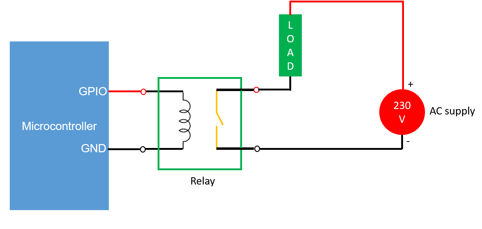
The simple way to control AC operated lights or AC or geyser is shown below diagram.

Relay
Relay provides two important functionalities and those are
- Acts as switch
- It provides isolation between the microcontroller and AC supply. The microcontroller works on DC supply and Light blub or geyser etc works on AC supply. Since GND of microcontroller and neutral of AC supply are not connected to each other hence there is isolation between the microcontroller and AC supply or load.
Relay as Switch:
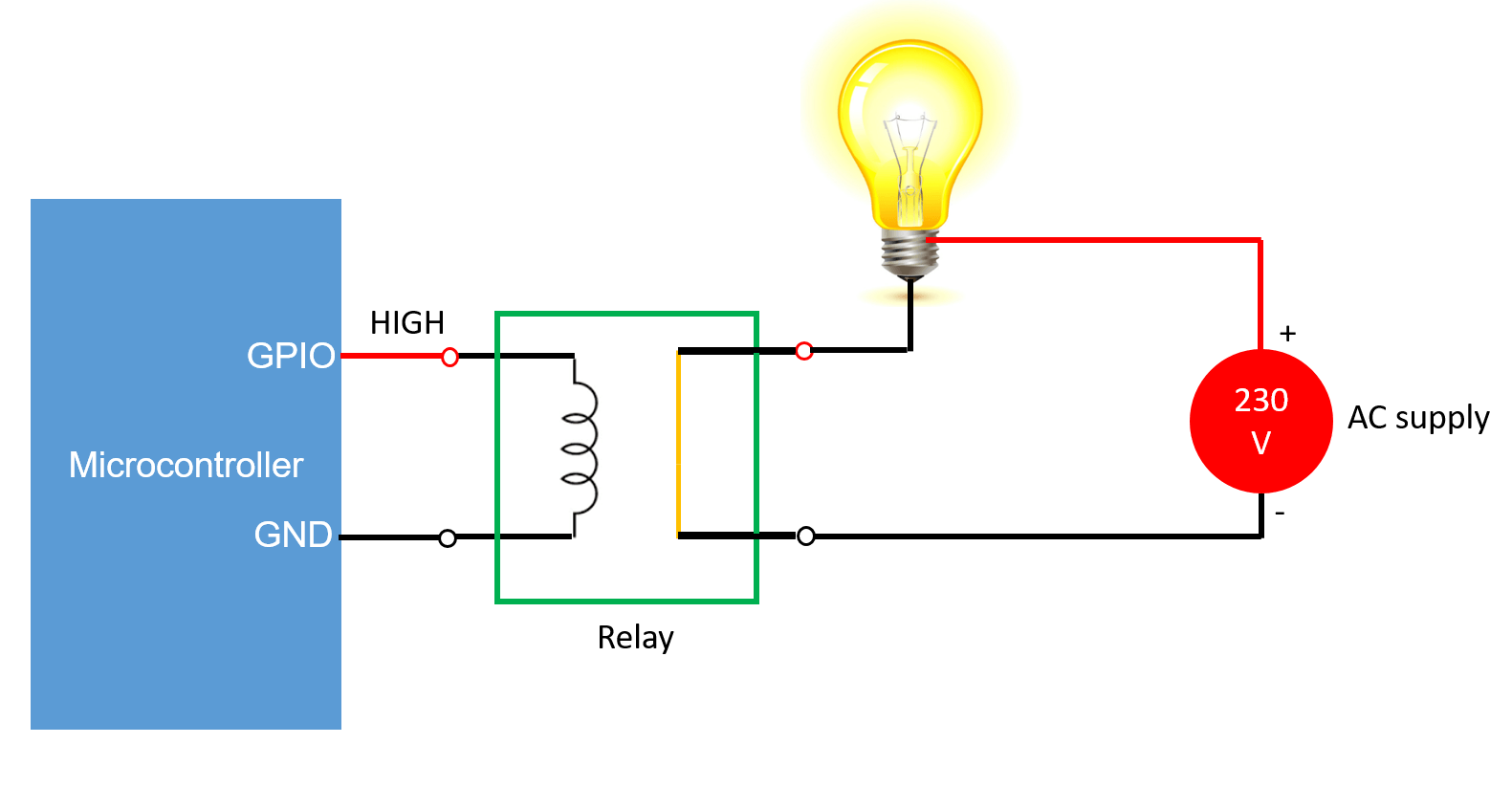
When the input to relay is logic 1 or VCC then current flows through the primary winding of relay and secondary winding gets short circuited which is shown below.
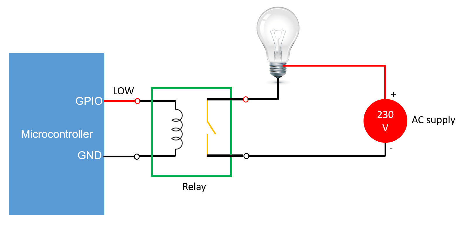
When the input to relay is logic 0 or GND then current does not flow through the primary winding of relay and secondary winding remains open circuited which is shown below.

How to control light with microcontroller Working
Connection:
- Connect microcontroller any GPIO pin to relay input pin with respect to ground.
- Connect light or blub between output side relay and AC supply which is shown below
Case 1: Assuming you have made the connections correctly
When you make GPIO HIGH or logic 1 current flows through the primary winding of relay and secondary winding of relay gets short circuited right. Electric blub is resistive (so do not have polarity) and it is connected between AC supply and output side of the relay which is shown below. So when secondary winding of relay is short circuited current will flow from the following path and blub will turn ON which is shown below.
230 V ( + ) -> Blub -> relay secondary winding -> 230 V ( – )

Case 2:
When you make GPIO LOW or logic 0 current does not flow through the primary winding of relay and secondary winding of relay remains open circuited right. Electric blub is resistive (so do not have polarity) and it is connected between AC supply and output side of the relay which is shown below. So when secondary winding of relay is open circuited current will not flow through the circuit and blub will turn OFF which is shown below.


